What are Some Commonly Used Core Types in Output Transformers?
Output transformers play a crucial role in audio and
power applications, efficiently transferring energy between primary and
secondary windings while maintaining impedance matching. These transformers
often utilize various core types, each with its unique characteristics and
advantages. Understanding the core types commonly employed in output
transformers can provide valuable insights into their design and performance.
In this article, we will explore three frequently used core types: EI cores,
C-cores, and Toroidal cores.
Table
of Contents
Introduction
EI Cores
2.1 Construction and Design
2.2 Advantages of EI Cores
2.3 Limitations of EI Cores
C-Cores
3.1 Construction and Design
3.2 Advantages of C-Cores
3.3 Limitations of C-Cores
Toroidal Cores
4.1 Construction and Design
4.2 Advantages of Toroidal Cores
4.3 Limitations of Toroidal Cores
Core Selection Considerations
Conclusion
FAQs
1.
Introduction
Output transformers are essential components in audio
amplifiers, power supplies, and other applications where energy conversion and
impedance matching are crucial. They consist of primary and secondary windings
wound around a magnetic core, which serves as the pathway for the magnetic
flux. The choice of core type significantly influences the transformer's
performance, including its frequency response, power handling capability, and
efficiency.
2.
EI Cores
2.1 Construction and Design
EI cores derive their name from their shape, which
resembles the letters "E" and "I." They consist of two
separate E-shaped laminations, forming a closed magnetic path when assembled
together with an I-shaped center leg. The windings are placed around the center
leg, allowing for efficient magnetic coupling.
2.2 Advantages of EI Cores
Cost-Effective: EI cores are widely available and
cost-effective, making them a popular choice for many applications.
Flexibility:
The separate E-shaped laminations allow for easy customization and adaptation
to specific design requirements.

Good Power Handling Capability: EI cores can handle
higher power levels due to their larger core area compared to other core types.
Efficient Cooling: The open structure of EI cores
facilitates better cooling and reduces the risk of overheating.
2.3 Limitations of EI Cores
Limited High-Frequency Performance: Due to their larger
air gaps and increased magnetic leakage, EI cores may exhibit limitations in
high-frequency response and efficiency.
Audible Noise: The interleaved design of EI cores can
lead to audible magnetostriction noise under certain conditions.
3.
C-Cores
3.1 Construction and Design
C-cores,
also known as UU cores, feature a distinctive C-shaped design. They consist of
two mirrored C-shaped laminations with a shared center leg, forming a closed
magnetic path. The windings are wound around the shared center leg, ensuring
efficient magnetic coupling.

3.2 Advantages of C-Cores
Compact Size: C-cores offer a compact design, making them
suitable for applications with space constraints.
Reduced Leakage Inductance: The shared center leg
design of C-cores helps minimize magnetic leakage and reduce leakage
inductance.
Improved High-Frequency Performance: C-cores exhibit
superior high-frequency response compared to EI cores, making them suitable for
applications demanding wide bandwidth.
3.3 Limitations of C-Cores
Lower Power Handling Capability: C-cores typically have
a smaller core area compared to EI cores, resulting in a lower power handling
capability.
Higher Cost: C-cores may be more expensive than EI
cores due to their specialized design and manufacturing process.
4.
Toroidal Cores
4.1 Construction and Design
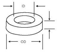
Toroidal
cores have a ring-like or doughnut shape and offer a continuous magnetic path.
They are constructed using a strip or tape of magnetic material wound into a
toroidal shape. The windings are uniformly distributed around the core,
resulting in excellent magnetic coupling.
4.2 Advantages of Toroidal Cores
High Efficiency: Toroidal cores provide high magnetic
coupling efficiency due to the absence of air gaps and reduced magnetic
leakage.
Compact Size: These cores offer excellent space
utilization, making them suitable for compact designs.
Low Audible Noise: The absence of air gaps and the
uniform distribution of windings minimize magnetostriction noise.
4.3 Limitations of Toroidal Cores
Complex Manufacturing Process: The manufacturing
process of toroidal cores is more intricate and time-consuming, contributing to
higher costs.
Limited Flexibility: Once wound, toroidal cores are
difficult to modify or customize, limiting their flexibility in certain design
scenarios.
5.
Core Selection Considerations
When selecting a core type for an output transformer,
several factors should be considered, including:
Frequency Response Requirements: Different core types
exhibit varying frequency responses. Consider the desired frequency range and
the core's ability to handle it efficiently.
Power Handling Capability: The power handling
capability depends on the core size, cross-sectional area, and material
properties.
Space Constraints: Evaluate the available space and
select a core type that fits within the designated dimensions.
Cost Considerations: Consider the budget and assess the
cost-effectiveness of different core options.
Manufacturing Complexity: Determine whether the chosen
core type aligns with the manufacturing capabilities and processes available.
6.
Conclusion
Output transformers rely on core types such as EI
cores, C-cores, and Toroidal cores to optimize their performance and achieve
efficient energy transfer. Each core type offers unique advantages and
limitations, making them suitable for specific applications and design
requirements. When selecting a core type, it is essential to consider factors
such as frequency response, power handling capability, space constraints, cost,
and manufacturing complexity. By understanding the characteristics of different
core types, engineers can design output transformers that meet their desired
performance specifications.
7.
FAQs
Q1: How can I calculate the inductance of a transformer
using magnetic formulas?
A: To calculate the inductance of a transformer, you
can employ the following magnetic formula: Lp = 1.257 x μe.N^2.Ac x 10^-9/Lc.
Here, Lp represents the primary inductance, N denotes the number of turns, Ac
represents the core's cross-sectional area, and Lc signifies the mean length of
the magnetic path. The value of μe relies on the magnetic flux density B, which
you can compute using the equation BAC = Vrms x 10^10/4.44.N.f.A. In this
equation, Vrms signifies the applied AC voltage to the transformer, N is the
number of turns, f denotes the frequency of operation, and A represents the
core's cross-sectional area.
Q2: What is the formula for determining inductance?
A: The formula for determining inductance is as
follows: Lp = 1.257 x μe.N^2.Ac x 10^-9/Lc. In this equation, Lp refers to the
primary inductance, N represents the number of turns, Ac signifies the core's
cross-sectional area, and Lc denotes the mean length of the magnetic path. The
value of μe depends on the magnetic flux density B, which can be calculated
using the equation BAC = Vrms x 10^10/4.44.N.f.A. Here, Vrms denotes the
applied AC voltage to the transformer, N represents the number of turns, f is
the frequency of operation, and A represents the core's cross-sectional area.
Q3: Does the formula for determining inductance account
for non-linear effects?
A: The provided formula for determining inductance does
not account for any non-linear effects that may occur at high magnetic flux
densities. It assumes linearity in the core material.
Q4: Why is core size important in audio transformer
design?
A: When designing an audio transformer, the physical
core size plays a significant role as it determines the transformer's power
handling capability and low-frequency limit. A larger core can accommodate more
power and provide a lower frequency response. However, it also increases
winding capacitance, which can limit the high-frequency bandwidth. The number
of sections used in the windings also impacts the high-frequency bandwidth,
with more sections resulting in lower leakage inductance but higher winding
capacitance. Consequently, selecting the appropriate core size and winding
configuration is crucial for achieving the desired performance characteristics
in an audio transformer.
Q5: How does winding capacitance affect bandwidth in an
audio transformer?
A: Winding capacitance restricts the bandwidth of an
audio transformer by constraining the high-frequency response. Capacitance is
formed between the windings and the core, creating a low-pass filter with the
transformer's inductance. As the frequency increases, the impedance of the
winding capacitance decreases, allowing more high-frequency energy to pass
through. This can lead to distortion and loss of detail in the audio signal.
Therefore, minimizing winding capacitance is vital to achieving a broad
bandwidth in an audio transformer.


.png)
Comments
Post a Comment